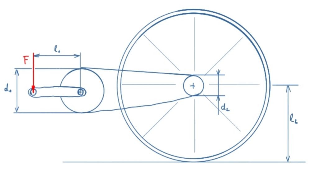
This is a statichttps://en.wikipedia.org/wiki/Statics investigation of the forces and moments at a bicycle powertrain. This means, we have have no functions depending on the rotation angle here.
Task
The force F acts on a pedal crank of a bicycle. The following parameters have to be determined
a) the moment on the crankshaft
b) the tensile force in the chain
c) the moment on the rear wheel
d) the propulsive force of the bicycle

Solution
The following video is in german language. Please scroll down for the written solution.
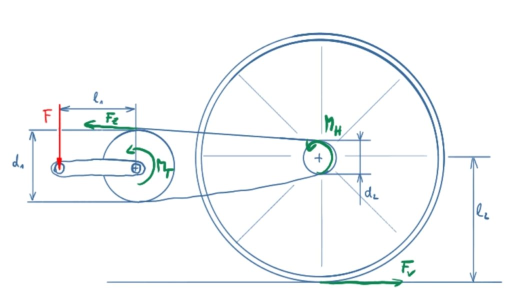
In the following, moments will be assigned as M and forces as F.
Solution sketch

The torque on the crankshaft is
\[\tag{1} M_T = F \cdot l_1 \]
The tensile force in the chain results from
\[\tag{2} F_Z = \frac{M_T}{\frac{d_1}{2}} = \frac{2 M_T}{d_1} = \frac{2 F l_1}{d_1} \]
The torque on the rear wheel is
\[\tag{3} M_H = F_Z \cdot \frac{d_2}{2} = \frac{\bcancel{2} F l_1}{d_1} \cdot \frac{d_2}{\bcancel{2}} = F l_1 \cdot \frac{d_2}{d_1} \]
The propulsive force on the rear wheel is
\[\tag{4} F_V = \frac{M_H}{l_2} = F \cdot \frac{l_1}{l_2} \cdot \frac{d_2}{d_1} \]
So these were the forces and moments at a bicycle powertrain. The real forces and moments are quite more complex to determine due to the geometrical conditions of the rotationg components. These kind of calculations are done in the Kinematics field of Mechanics.
Maybe this static consideration of a crank drive is interesting for you?

