
This exercise is about the following questions:
- How to determine the internal forces of a beam?
- How to visualize the gradient of internal forces of a beam?
- How to calculate the bending moment of a beam?
- How to calculate the shear force and the normal force of a beam?
Task
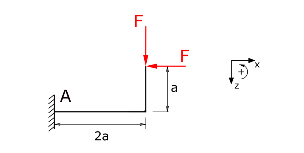
A bent cantilever beam is fixed in A and under load of two forces F in different directions. The internal forces and moments of the beam have to be determined and visualized!
Solution
The beam will be divided into two section because the functions (and gradients) for the bending moments in these two sections are different. This is caused by the bent shape of the beam.
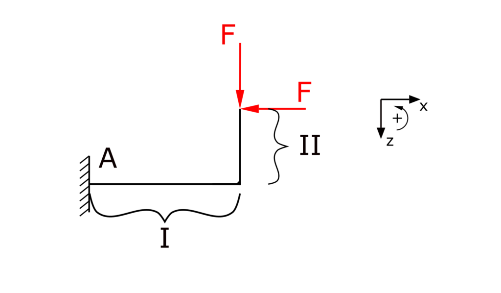
The sections will be referred to as I and II.
In this solution the internal forces will be represented as Fx and Fy. These forces (this means the directions x and z, not the index I or II) stand both once for the normal force and the shear force in both sections, due to the bent shape of the beam. (The normal force and the shear force may be referred to as N and S in other exercises.) The bending moment is called Mb here.
The free body diagrams in the sections I and II are carried out without the need for the determination of the bearing reaction of the fixation A.
Section I
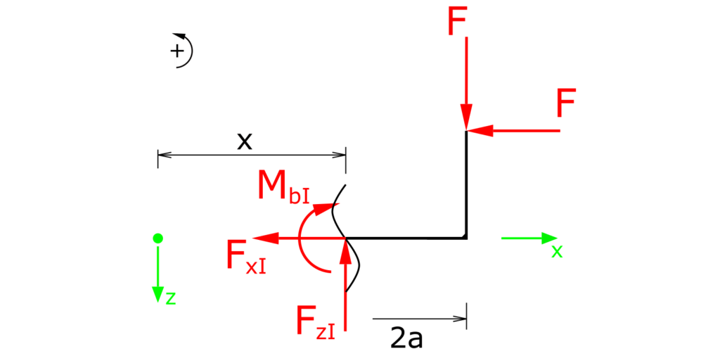
Establishing the equilibrium conditions for forces in the x and z directions as well as for the moments in section I:
\[ \tag{1} \sum F_x = 0 = -F_{xI} - F\]
\[ \tag{2} \sum F_z = 0 = F_{zI} - F\]
\[ \tag{3} \sum M_b(x) = 0 = - M_{bI} - F \cdot (2a - x) + F \cdot a \]
The two forces in the x and z directions are constant over the entire range I. The bending moment in section I is a function of x.
\[ \tag{4} F_{xI} = - F\]
\[ \tag{5} F_{zI} = F\]
\[ \tag{6} M_{bI} = F \cdot (x-a) \]
Section II
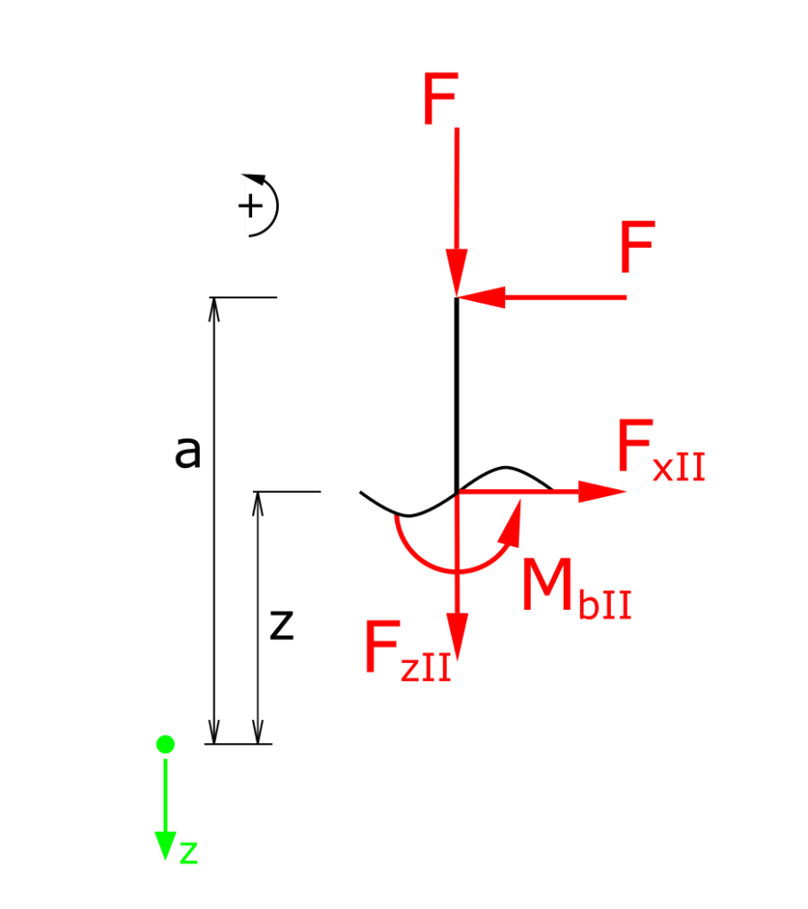
Establishing the equilibrium conditions for forces in the x and z directions as well as for the moments in section II:
\[ \tag{7} \sum F_x = 0 = F_{xII} - F\]
\[ \tag{8} \sum F_z = 0 = -F_{zII} - F\]
\[ \tag{9} \sum M_b(x) = 0 = M_{bII} + F \cdot (a - z) \]
The two forces in the x and z directions are constant over the entire range II. The bending moment in section II is a function of z.
\[ \tag{10} F_{xII} = F\]
\[ \tag{11} F_{zII} = - F\]
\[ \tag{12} M_{bII} = F \cdot (z-a) \]
Graphic representation of the internal forces
With the functions determined above, the following representation of the gradients of shear force, normal force and bending moment results. The diagrams are rotated 90 ° for the upward part of the beam.
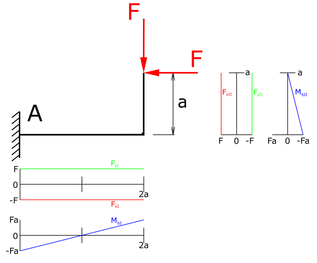
This means that all internal forces of the beam are determined and visualized.
Here we have a collection of more exercises and solutions regarding the strength of material/Engineering Mechanics II.