
This exercise is about the following questions:
- How to determine the internal forces of a beam under single loads?
- How to calculate the function of the bending moment?
- Where do I have to divide the beam into sections for the calculation?
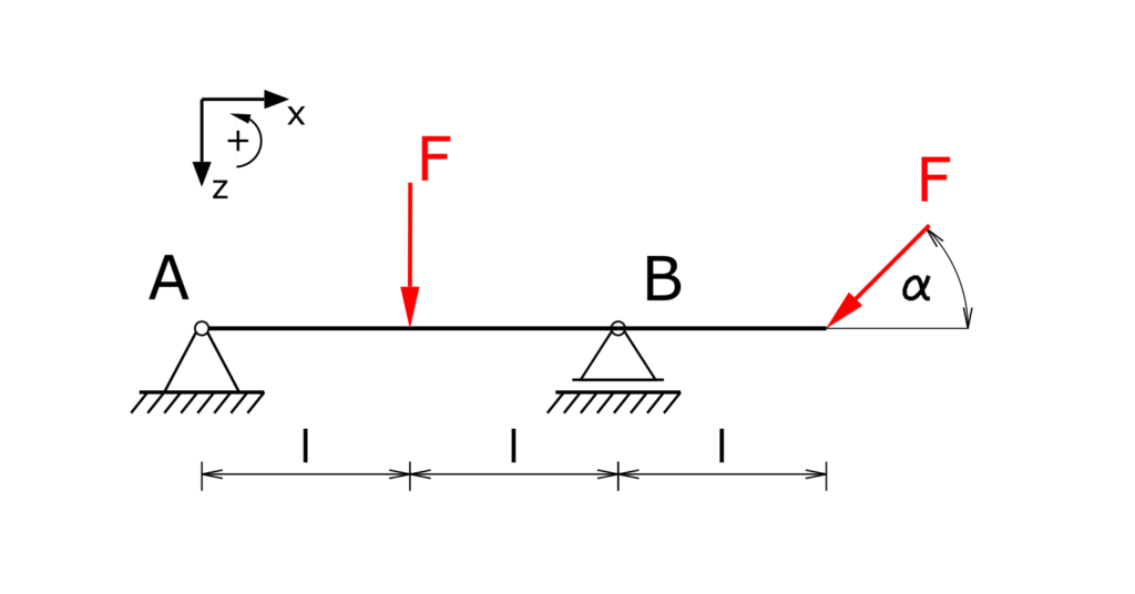
Task
A beam with an exceeding end is mounted on two supports and is loaded once vertically and once at an angle by the force F. The beam itself is not interrupted in the floating bearing B. The bearing reactions and the internal forces have to be determined!
Solution
The beam is cut free and the bearing reactions are noted. Left turning moments are accepted positively. Note the downward z-axis!
The beam is divided into three sections as shown.
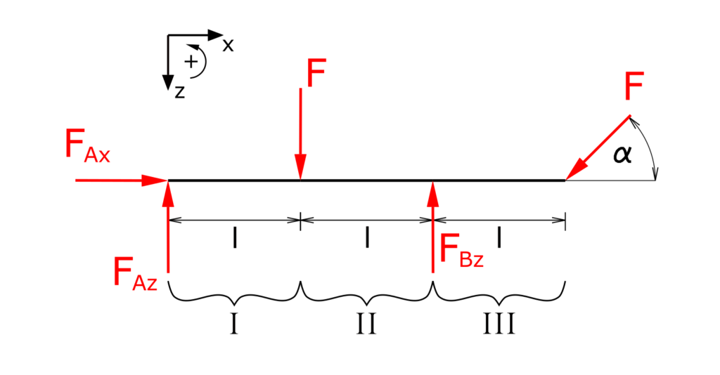
Determination of the bearing loads
Establishing the equilibrium conditions for forces in the x and z directions as well as for the moments:
\[ \tag{1} \sum F_x = 0 = F_{Ax} - F \cdot cos \alpha\]
\[ \tag{2} \sum F_z = 0 = - F_{Az} +F -F_{Bz} + F \cdot sin \alpha \]
\[ \tag{3} \sum M(A) = 0 = -F\cdot l +F_{Bz} \cdot 2 l - F \cdot sin \alpha \cdot 3 l \]
FBz can thus be determined directly.
\[ \tag{4} F_{Bz} =F \cdot \frac{ 1 + 3 \cdot sin \alpha }{2} \]
Then the first two equations are solved for FAx and FAz.
\[ \tag{5} F_{Ax} = F \cdot cos \alpha\]
\[ \tag{6} F_{Az} = F - F \cdot \frac{ 1 + 3 \cdot sin \alpha }{2} + F \cdot sin \alpha \]
\[ \tag{7} F_{Az} = \frac{F}{2} \cdot \left( 1 - sin \alpha \right) \]
Determination of the internal forces
It is beneficial to choose the cutting direction in the respective sections or areas so that the equations can be kept as simple as possible. In this case this means that the first section on the right is cut off, the two following sections are cut off on the left. The sections considered are marked in green for clarity. In the following, normal forces are denoted by N, transverse forces by Q and the bending moment by Mb.
Section I
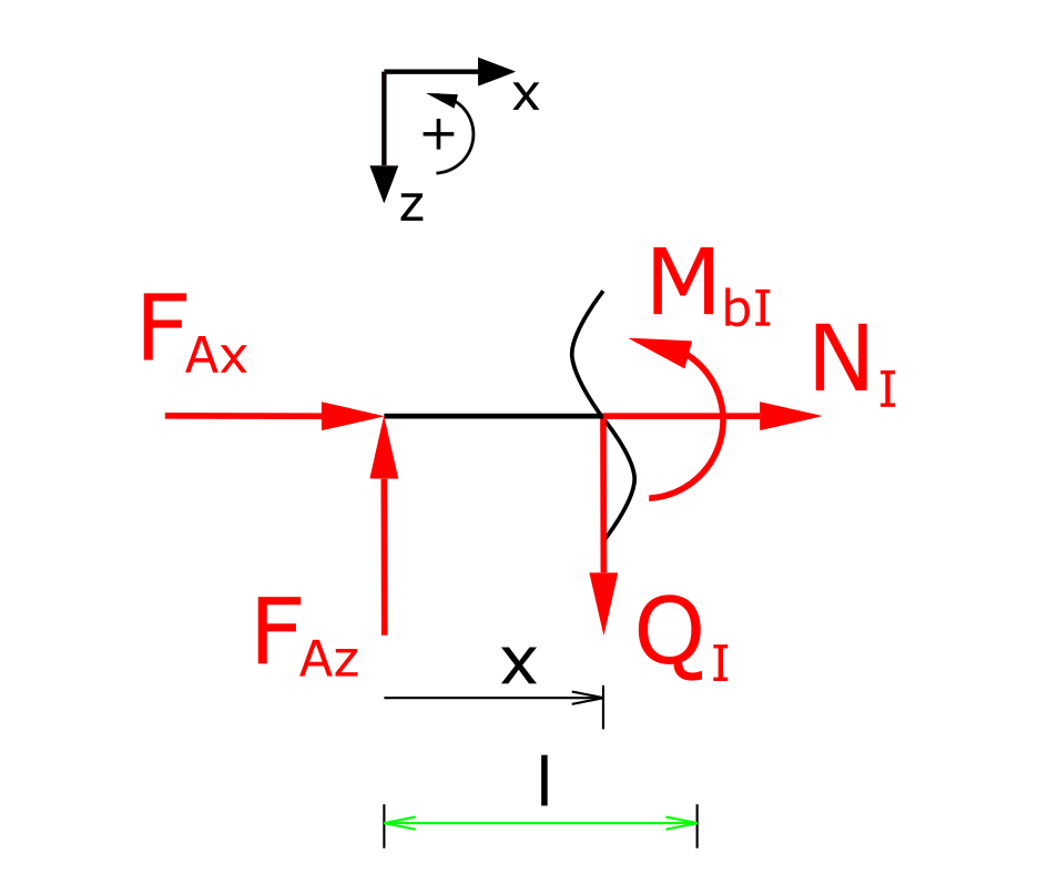
Establishing the equilibrium conditions for forces in the x and z directions as well as for the moments:
\[ \tag{8} \sum F_x = 0 = F_{Ax} + N_I \]
\[ \tag{9} \sum F_z = 0 = -F_{Az} + Q_I \]
\[ \tag{10} \sum M(x) = 0 = -F_{Az} \cdot x + M_{bI} \]
The already known bearing loads are now used:
\[ \tag{11} N_I = - F \cdot cos \alpha \]
\[ \tag{12} Q_I = \frac{F}{2} \cdot \left( 1 - sin \alpha \right) \]
\[ \tag{13} M_{bI} = \frac{F}{2} \cdot \left( 1 - sin \alpha \right) \cdot x \]
Section II
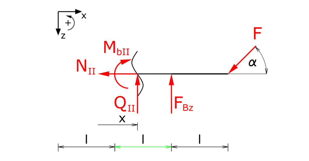
This section is investigated opposite to section I. This means that the internal forces are drawn negatively here.
Establishing the equilibrium conditions for forces in the x and z directions as well as for the moments:
\[ \tag{14} \sum F_x = 0 = -N_{II} - F \cdot cos \alpha \]
\[ \tag{15} \sum F_z = 0 = -Q_{II} - F_{Bz} + F \cdot sin \alpha \]
\[ \tag{16} \sum M(x) = 0 = -M_{bII} + F_{Bz} \cdot (2l-x) - F \cdot sin \alpha \cdot (3l-x) \]
The already known support force FBz is now used so that all internal forces in section II can be determined:
\[ \tag{17} N_{II} = F \cdot cos \alpha \]
\[ \tag{18} Q_{II} = - F \cdot \frac{ 1 + 3 \cdot sin \alpha }{2} + F \cdot sin \alpha \]
\[ \tag{19} Q_{II} = - \frac{F}{2} \cdot (1 + sin \alpha) \]
\[ \tag{20} M_{bII} = F \cdot \frac{ 1 + 3 \cdot sin \alpha }{2} \cdot (2l-x) - F \cdot sin \alpha \cdot (3l-x) \]
\[ \tag{21} M_{bII} = \frac{F}{2} \cdot \left( 2l - x - \sin \alpha\cdot x \right) \]
Section III
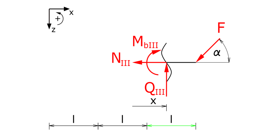
Establishing the equilibrium conditions for forces in the x and z directions as well as for the moments:
\[ \tag{22} \sum F_x = 0 = -N_{III} - F \cdot cos \alpha \]
\[ \tag{23} \sum F_z = 0 = -Q_{III} + F \cdot sin \alpha \]
\[ \tag{24} \sum M(x) = 0 = -M_{bIII} - F \cdot sin \alpha \cdot (3l-x) \]
The internal forces of section III are:
\[ \tag{25} N_{III} = - F \cdot cos \alpha \]
\[ \tag{26} Q_{III} = F \cdot sin \alpha \]
\[ \tag{27} M_{bIII} = - F \cdot sin \alpha \cdot (3l-x) \]
This means that all support reactions and internal forces of the beam are determined.
Here we have some more interesting exercises and solution regarding Engineering mechanics II - theory of materials.