
This exercise shows how to calculate the bearing loads and the internal forces for a beam with triangular line load.
Task
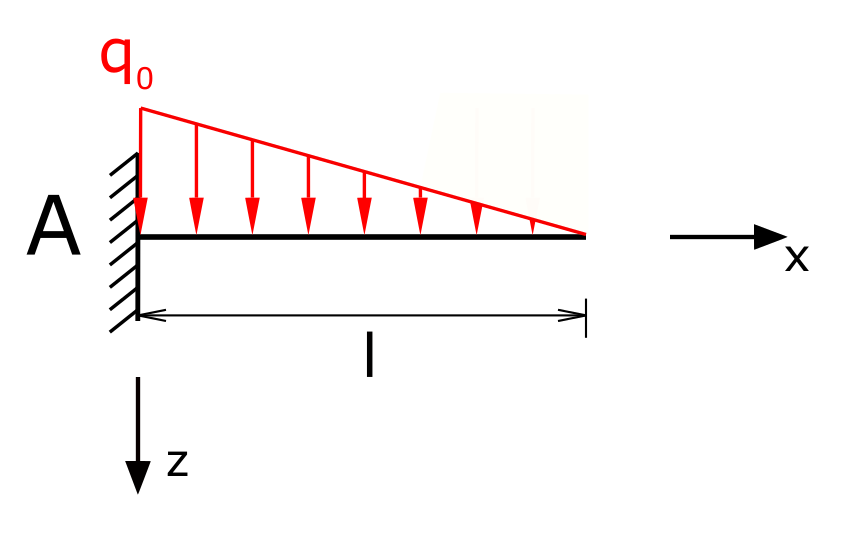
A beam with a fixed restraint on one side is loaded with a triangular line load. The load sizes and the internal forces have to be determined!
The function for the line load is
\[ q(x) = q_0 \cdot \left( 1 - \frac{x}{l} \right) \]
Solution
Since the entire beam is loaded by the line load, no division of the beam into sections is required. In order to be able to calculate the internal forces, the support reactions do not necessarily have to be determined (in this case!). This depends on how the cuts are made, i.e. which area of the beam is being "cut off". In the solution shown here, the sections are placed in such a way that the support reactions are not contained in the force equilibria of the internal forces. Nevertheless, for the sake of completeness, the reactions of the fixed restraint are calculated in the first step.
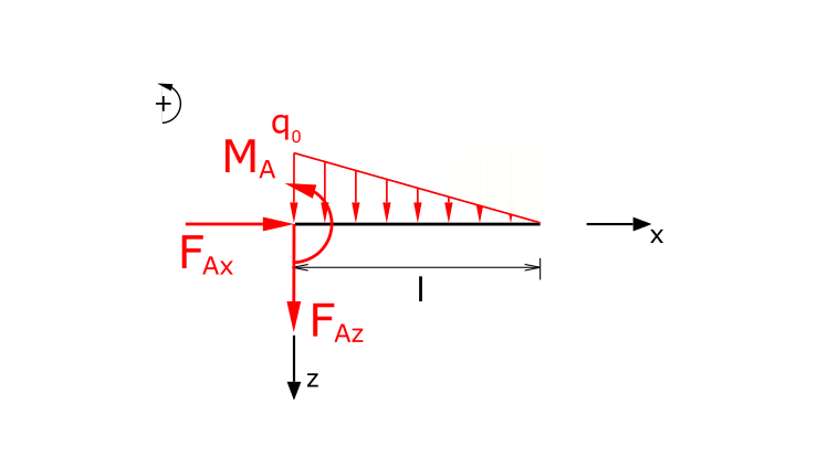
The establishment of the equilibrium of forces in the x and z directions as well as the equilibrium of moments (counterclockwise torques positive) leads to:
\[ \tag{1} \sum F_x = 0 = F_{Ax} \]
\[ \tag{2} \sum F_z = 0 = F_{Az} +\int_{0}^{l}{q_0 \cdot \left( 1 - \frac{x}{l} \right)\,dx} \]
\[ \tag{3} \sum M(A) = 0 = M_A - \int_{0}^{l}{q_0 \cdot \left( 1 - \frac{x}{l} \right) \cdot x\,dx} \]
The support reactions of the fixed restraint can thus be determined directly
\[ \tag{4} F_{Ax} = 0 \]
\[ \tag{5} F_{Az} = - \frac{q_0 \cdot l}{2} \]
\[ \tag{6} M_A = \frac{q_0 \cdot l^2}{6} \]
Determination of the internal forces
In the following, shear forces are referred to as Q, normal forces as N and bending moments as Mb.
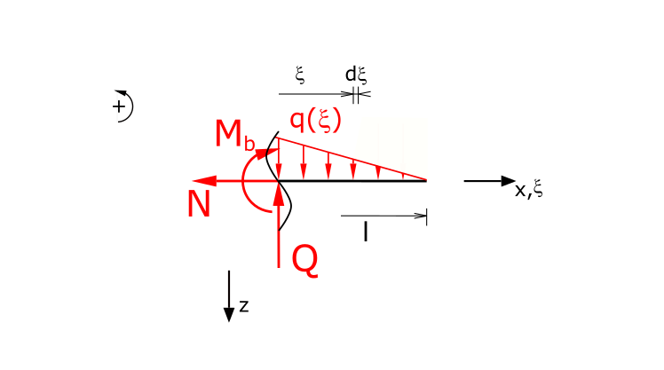
Establishing the equilibrium of forces in the x and z directions as well as the equilibrium of moments (the line load is now calculated using the auxiliary coordinate ξ!):
\[ \tag{7} \sum F_x = 0 = -N \]
\[ \tag{8} \sum F_z = 0 = -Q +\int_{x}^{l}{q_0 \cdot \left( 1 - \frac{\xi}{l} \right)\,d\xi} \]
\[ \tag{9} \sum M(x) = 0 = - M_b - \int_{x}^{l}{q_0 \cdot \left( 1 - \frac{\xi}{l} \right) \cdot \left( \xi - x \right) \,d\xi} \]
The normal force is quickly determined:
\[ \tag{10} N = 0 \]
The function of the shear force results from
\[ \tag{11} Q = \left[ q_0 \cdot \left( \xi - \frac{\xi^2}{2 \cdot l} \right) \right]_{x}^{l} \]
\[ \tag{12} Q = q_0 \cdot \left( l - \frac{l^2}{2 \cdot l} \right) - q_0 \cdot \left( x - \frac{x^2}{2 \cdot l} \right) \]
\[ \tag{13} Q = q_0 \cdot \left( \frac{x^2-2 \cdot l \cdot x}{2 \cdot l} + \frac{l}{2} \right) \]
And, finally, the bending moment:
\[ \tag{14} M_{b} = \frac{{q_0} {{x}^{3}}-3 l\, {q_0} {{x}^{2}}+3 {{l}^{2}}\, {q_0} x-{{l}^{3}}\, {q_0}}{6 l} \]
The function can easily be checked at this point. At the point x = 0, the bending moment must correspond to the support reaction MA.
\[ \require{cancel} \]\[ \tag{15} M_{b}(x=0) = \frac{{q_0} {{0}^{3}}-3 l\, {q_0} {{0}^{2}}+3 {{l}^{2}}\, {q_0} 0-{{l}^{3}}\, {q_0}}{6 l} \]
\[ \tag{16} M_{b}(x=0) = - q_0 \cdot \frac{l^2}{6} \]
The result is the same. The negative sign arises from the differently assumed directions of rotation for the two moments.
This exercise is part of the collection Engineering Mechanics II.