
This exercise addresses the following questions:
- How to calculate the resulting moment with a line load?
- How to calculate the internal forces for a line load?
- How to calculate a beam with partial line load?
Task
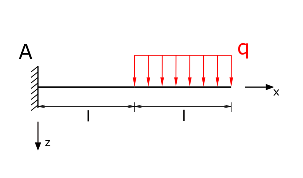
A beam with a fixed restraint in A is loaded over half of its length by the uniform line load q. The internal forces are to be determined!
Solution
The beam is divided into two sections. In order to be able to calculate the internal forces, the support reactions do not necessarily have to be determined. This depends on how the cuts are made, i.e. which area of the carrier is being "cut off". In the solution shown here, the cuts are placed in such a way that the support reactions are not included in the equilibrium of forces. Nevertheless, for the sake of completeness, the bearing reactions are calculated in the first step.
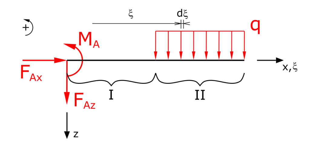
The line load is calculated along the auxiliary coordinate ξ. The establishment of the equilibrium of forces in the x and z directions as well as the equilibrium of moments (counterclockwise torques positive) leads to:
\[ \tag{1} \sum F_x = 0 = F_{Ax} \]
\[ \tag{2} \sum F_z = 0 = F_{Az} +\int_{l}^{2l}{q\,d\xi} \]
\[ \tag{3} \sum M(A) = 0 = M_A - \int_{l}^{2l}{q \xi \,d\xi} \]
The bearing reactions of the fixed restraint can thus be determined directly
\[ \tag{4} F_{Ax} = 0 \]
\[ \tag{5} F_{Az} = - q \cdot l \]
\[ \tag{6} M_A = \frac{3}{2} \cdot q \cdot l^2 \]
Determination of the internal forces
In the following, shear forces are referred to as Q, normal forces as N and bending moments as Mb.
Section I
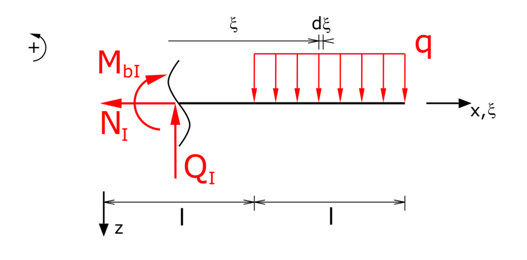
Establishing the equilibrium of forces in the x and z directions as well as the equilibrium of moments:
\[ \tag{7} \sum F_x = 0 = -N_I \]
\[ \tag{8} \sum F_z = 0 = -Q_I +\int_{l}^{2l}{q\,d\xi} \]
\[ \tag{9} \sum M(x) = 0 = - M_{bI} - \int_{l}^{2l}{q \cdot (\xi - x) \,d\xi} \]
This results in the internal forces in section I:
\[ \tag{10} N_I = 0 \]
\[ \tag{11} Q_I = q \cdot l \]
\[ \tag{12} M_{bI} = - \frac{q \cdot l}{2} \cdot \left( 2 \cdot x - 3 \cdot l \right) \]
Section II
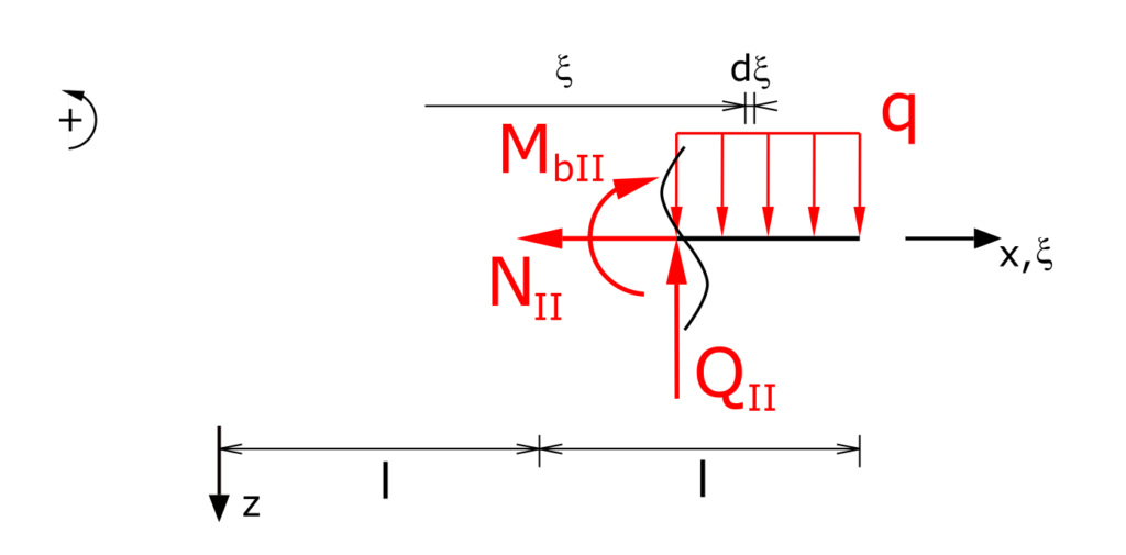
Establishing the equilibrium of forces in the x and z directions as well as the equilibrium of moments:
\[ \tag{13} \sum F_x = 0 = -N_{II} \]
\[ \tag{14} \sum F_z = 0 = -Q_{II} +\int_{x}^{2l}{q\,d\xi} \]
\[ \tag{15} \sum M(x) = 0 = - M_{bII} - \int_{x}^{2l}{q \cdot (\xi - x) \,d\xi} \]
This results in the internal forces in section II:
\[ \tag{16} N_{II} = 0 \]
\[ \tag{17} Q_{II} = q \cdot (2\cdot l - x) \]
\[ \tag{18} M_{bII} = - q \cdot \left( \frac{x^2}{2} - 2 \cdot l \cdot x + 2 \cdot l^2 \right) \]
With this all internal forces of the beam are determined. This exercise is part of the Engineering Mechanics II - Strength of Materials collection.