
This article lists various thermal considerations on a design example ("device"). The steps shown here serve as a rough design in development and construction, such as how they can be used, for example, to define a specific cooling concept for devices with heat sources.
The starting point
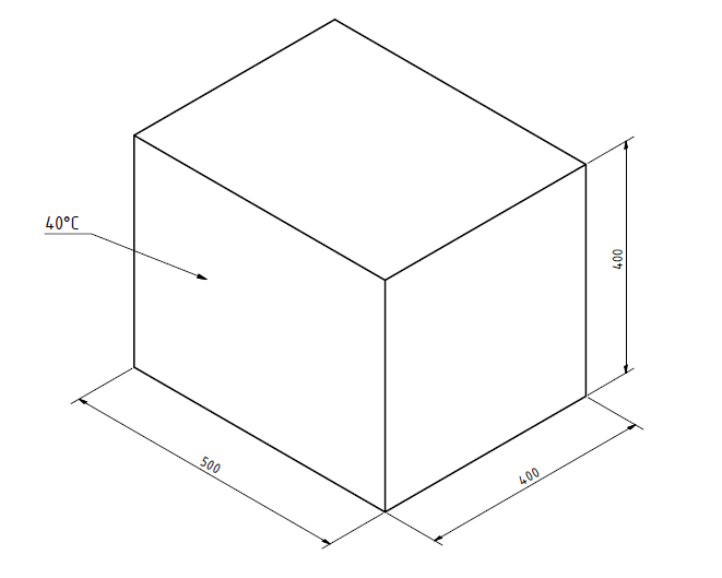
A device is to be developed in which, among other things, a heat source (e.g. power electronics) is located. To ensure safe operation, a certain housing temperature should not be exceeded. The outer shape of the device largely resembles a cuboid. The dimensions are already fixed and are:
Length: 400 mm
Height: 400 mm
Width: 500 mm
The housing material should be an aluminum alloy with a thickness of 5 mm. The thermal power of the heat source is 600 W. The heat source is arranged in the middle and the air can move freely inside the device. The installation site of the device is calm with a maximum ambient temperature of 30 ° C. It is largely accessible from all sides, i.e. it does not stand on a surface.
The following questions arise:
A) Can a maximum case temperature of 40 ° C be maintained?
B) Do constructive measures for cooling have to be provided?
Solution approach
The following approach assumes an equal distributed heat to all surfaces of the device.
Checking the heat flows
The device will heat up during operation until the equilibrium between the output and input heat is achieved, i.e. it is then a stationary heat transfer.
To simplify the calculation, the first step is to estimate how large the power emitted by thermal radiation is. Since a specific operating point is given with the maximum permissible housing temperature, the heat flow through radiation can be calculated for this.
Thermal radiation
The equation for calculating the radiant heat is
\[ P_R = \epsilon \cdot \sigma \cdot A \cdot T^4 \]
The emission figures for the housing material at the temperature to be considered are therefore required. At lower temperatures, the emission numbers can be viewed as constant, so that the following values are used for the present case (for aluminum anodized at 70 ° C from this source).
\[ \epsilon_{min} = 0.67\]
\[ \epsilon_{max} = 0.95\]
The Stefan-Boltzmann constant is
\[ \sigma = 5.670374419 \cdot 10^{-8} \frac{W}{m^2K^4} \]
And the surface of the device is
\[ A = 1.12m^2 \]
This means that the heat flow through radiation is in a range of
\[ P_R = 409 ... 580W \]
This means that the emission of heat through radiation alone is not sufficient. It must be considered whether the remaining heat output can be dissipated by free convection.
Convection
In order to maintain the maximum housing temperature, the following heat output would have to be dissipated by convection.
\[ P_{Creq} = 600 W - 409 W = 191 W \]
The equation for calculating the heat flow by convection is
\[ P_{C} = \alpha \cdot A \cdot \Delta T \]
The heat transfer coefficient for air (or in general for gases) with free convection is between
\[ \alpha_{min} = 3 \frac{W}{m^2K}\]
\[ \alpha_{max} = 20 \frac{W}{m^2K} \]
The temperature difference between the housing wall and the ambient air is
\[ \Delta T = 10 K \]
This means that the heat flow actually dissipated by convection is in the range of
\[ P_{C} = 34 ... 224 W \]
This means that in the worst case the surface temperature will rise above the desired 40 ° C.
Constructive measures
Various constructive measures are conceivable to dissipate the heat. A simple approach is to increase the surface area.
In order to determine the necessary area, the equations for the heat flow through convection and the heat flow through radiation are now combined to form a total heat flow and the most unfavorable coefficients are used (this overall calculation could also be used straight away
at the beginning to determine the resulting temperature difference). The given power of the heat source is used as the heat flow, the equation can then be changed according to the required area.
\[ P_{total} = α_{min} \cdot A_{req} \cdot ΔT + A_{req} \cdot T^4 \cdot ε_{min} \cdot σ \]
\[ A_{req} = 1.52 m^2 \]
How can this be implemented constructively? A cheap solution would be to design the side walls as cooling fins. However, this means that additional installation space is required.
Suppose a cooling fin is 10 mm deep and 2 mm wide. This is the area that it also contributes to the existing geometry
\[ A_{F} = 8000mm^2 \]
The necessary number of cooling fins results from
\[ n_{F} = \frac{A_{req}-A}{A_F} \approx 50 \]
These cooling fins can be distributed anywhere on the side walls of the device. Compact on one page it could look like this, for example:
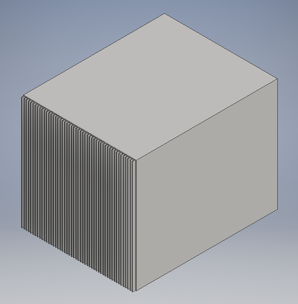
The heat dissipation to the outside would thus be solved. But is that enough?
Checking the internal temperature
In order to reach a surface temperature of 40° C, the heat has to overcome the thermal resistance of the outer wall. To do this, the inside temperature must be higher than the outside temperature. It is a heat transfer through a flat wall, which can be calculated according to the following equation.
\[ P_{total} = k \cdot A \cdot \left( T_i - T_o \right) \]
Ti is the inside temperature, To the outside temperature. The term kA is calculated from the sum of the individual resistances; here it must again be taken into account that the heat transfer coefficients can assume minimum and maximum values.
\[ \frac{1}{k \cdot A} = \frac{1}{\alpha_i A} + \frac{\delta}{\lambda A} + \frac{1}{\alpha_o A} \]
The thermal conductivity for aluminum is approx. 200 W / (mK), δ is the wall thickness of the housing wall with 5 mm. With these values, the following possible internal temperatures result, particularly depending on the heat transfer coefficient
\[ T_i = 79°C ... 303°C \]
Whether these values are permissible depends on what is supposed to happen inside the device. In the case of electronic components, values of 65 ° C should not be exceeded, i.e. in this case active cooling, i.e. possibly a fan, would have to be used in any case. If a fan is used, the cooling fins described above could then also be dispensed with, in particular since the movement of air on the inner wall of the housing results in a more favorable heat transfer coefficient.
Determination of the required air flow
It makes sense to also set a limit value for the temperature of the exhaust air. As an approximation to the maximum permissible surface temperature, 50° C is selected here. This means that the temperature range for the removal of heat is 20 K. With the specific heat capacity of cp = 1.001 kJ / (kgK) and a density of ρ = 1.293 kg / m3 for air (one could still look more closely here depending on the air humidity perform) the following volume flow results:
\[ P_{total} = \dot{V} \cdot \rho \cdot c_p \cdot \Delta T \]
\[ \dot{V} = 0.023 \frac{m^3}{s} \]
Assuming a fan diameter of 150 mm, the flow velocity is thus v = 1.3 m / s. These values are within a reasonable range, especially since it is to be expected that not all of the heat output has to be dissipated via the fan.
Summary
This completes the rough determination of the thermal conditions. The required temperatures can be maintained if active air cooling with a fan is used.
A simulation calculation should be used for more detailed considerations.