A machine base is an elementary component of many machines and systems.
In this article, various constructive designs of machine bases (machine feet or mountings) are shown. The variants shown here can be used in the construction of frames, devices, units and machines of all kinds. In the examples it is assumed that the machine frame is made from a hollow profile or with an U-profile.
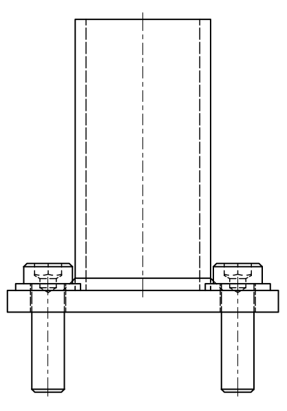
Variant 1 - base plate with through holes
Machine base variant 1 - with through holes
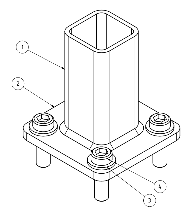
Machine base variant 1 - with through holes, isometric view
Variant 1 consists of an end plate that is welded to the hollow profile with a fillet weld. The front plate has 4 through-holes for the fastening screws.
Components used
Pos.-No.
Designation
Comment
1
Hollow profile
2
Front plate
with 4 through holes
3
Washer
4
Screw
Advantages and disadvantages
Advantages
Disadvantages
easy to manufacture
no compensation for unevenness
safe against lifting loads
no vibration damping
can transmit moments
no height adjustment
Variant 2 - with level adjustment
Machine base variant 2 - with level adjustment
Machine base variant 2 - with level adjustment, isometric view
Variant 2 essentially corresponds to the first variant, but has additional threaded holes in the faceplate. The adjusting screws are screwed into these threaded holes. It is ideal to cast this machine base after the height adjustment, e.g. with reaction resin concrete.
Components used
Pos.-No.
Designation
Comment
1
Hollow profile
2
Face plate
with 4 through holes and 4 threaded bores
3
Washer
4
Screw
5
Screw
for level adjustment
Advantages and disadvantages
Advantages
Disadvantages
easy to manufacture
no vibration damping
safe against lifting loads
no height adjustment
can transmit moments
compensation of unevenness
Variant 3 - internal face plate and purchased component
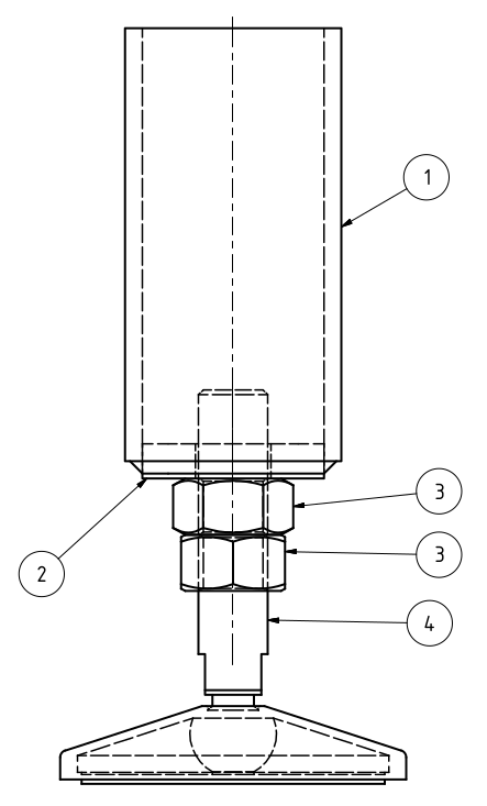
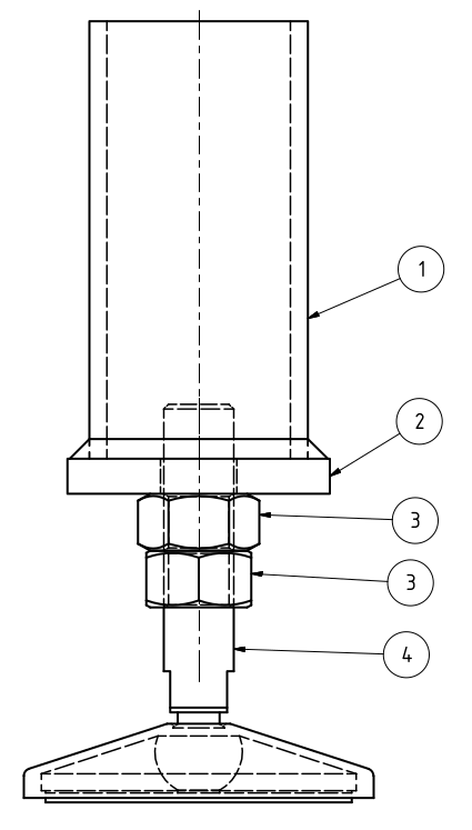
Machine base variant 3 - with purchased part and internal face plate
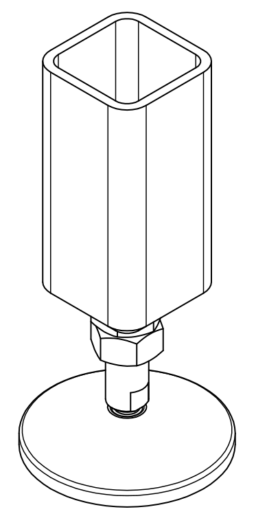
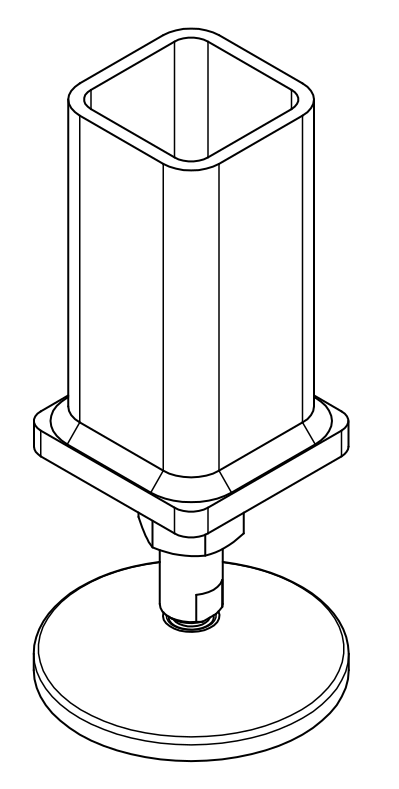
Machine base variant 3 - with purchased part and internal face plate, isometric view
Variant 3 consists of an end plate with a through hole onto which a nut has been welded. The finished foot is screwed in and locked from below.
Variant 4 - attached front plate with purchased part
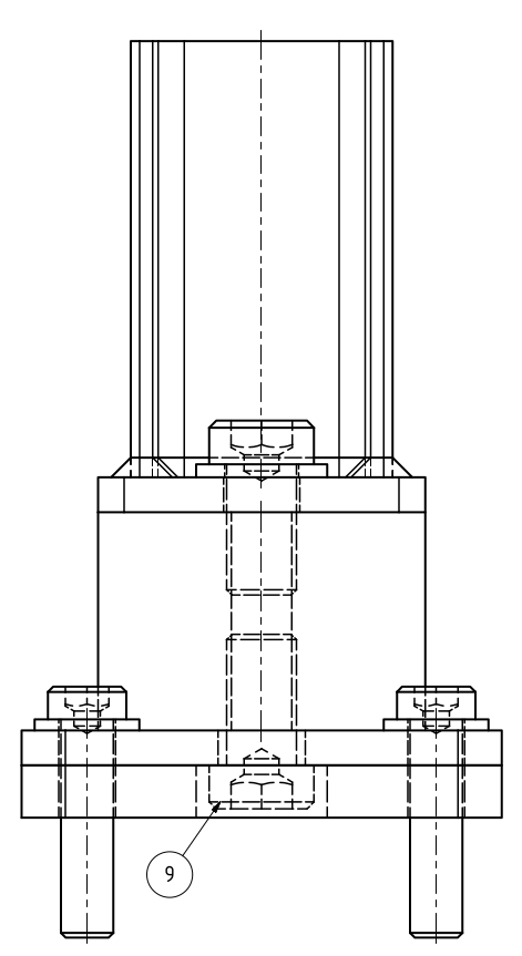
Machine base variant 4 - with purchased part and attached front plate
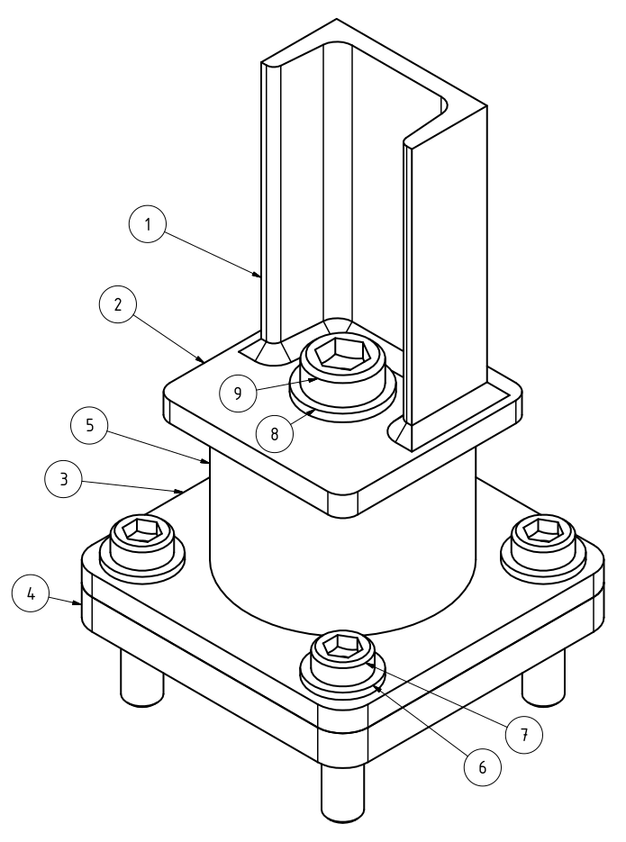
Machine base variant 4 - with purchased part and attached front plate, isometric view
Variant 4 essentially corresponds to variant 3, with the difference that the end plate is larger and is placed on the hollow profile instead of being embedded. This variant is a little easier to manufacture than variant 3.
Machine foot variant 5 - with shock absorber, isometric view
In this variant, the frame consists of an U-profile instead of a hollow profile. A shock absorber (or vibration damper) with a threaded hole on both sides is used. There is also a spacer plate below the base plate to cover the lower fastening screw for the mounting of the shock absorber.
We use cookies on our website to give you the most relevant experience by remembering your preferences and repeat visits. By clicking “Accept all”, you consent to the use of ALL the cookies.
This website uses cookies to improve your experience while you navigate through the website. Out of these, the cookies that are categorized as necessary are stored on your browser as they are essential for the working of basic functionalities of the website. We also use third-party cookies that help us analyze and understand how you use this website. These cookies will be stored in your browser only with your consent. You also have the option to opt-out of these cookies. But opting out of some of these cookies may affect your browsing experience.