
This exercise is about the calculation of the resultant force in a concurrent force system and addresses the following questions:
- How to calculate the components of a force?
- When do I use sine or cosine for angle calculation?
- How to determine the angle of a resulting force?
- How to determine the resulting force the graphical way?
Here is an online calculation tool for your assistance.
Task
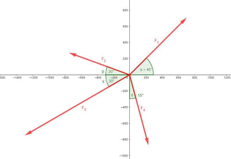
There are four forces acting on a power line pole in the horizontal plane. Calculate the resultant force for the following parameters:
F1 = 1.000 N, α = 45°F2 = 800 N, β = 20°
F3 = 1.500 N, γ = 30°
F4 = 900 N, δ = 15°
Solution
The following video is in German language. Please scroll down for the written version.

Calculation of the resultant force
The resultant force is called FR in this calculation. So the component of the resultant force in x-direction is FRx and the component in y-direction is FRy. The components of the resultant force are equal to the sum of the concurrent forces in each direction.
\( \DeclareMathOperator{\abs}{abs} \newcommand{\ensuremath}[1]{\mbox{$#1$}} \)
\[\tag{1} {F_{\mathit{Rx}}}={F_4} \sin{\left( \delta \right) }-{F_3} \cos{\left( \gamma \right) }-{F_2} \cos{\left( \beta \right) }+{F_1} \cos{\left( \alpha \right) }\]
\[\tag{2} {F_{\mathit{Ry}}}=-{F_4} \cos{\left( \delta \right) }-{F_3} \sin{\left( \gamma \right) }+{F_2} \sin{\left( \beta \right) }+{F_1} \sin{\left( \alpha \right) }\]
\[\tag{3} {F_R}=\sqrt{{{{F_{\mathit{Ry}}}}^{2}}+{{{F_{\mathit{Rx}}}}^{2}}}\]
\[\tag{4} \epsilon =\operatorname{atan}\left( \frac{{F_{\mathit{Ry}}}}{{F_{\mathit{Rx}}}}\right) \]
\[\tag{5} {F_{\mathit{Rx}}}=-1110.7 N\]
\[\tag{6} {F_{\mathit{Ry}}}=-638.6 N\]
\[\tag{7} {F_{\mathit{R}}}=1.281 N\]
\[\tag{8} \epsilon =29.9°\]
There is another way how to determine the resultant force for two or more forces. It is the
Graphical determination of the resultant force
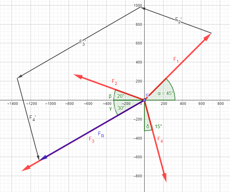
The individual forces have to be drawn to scale (!). The easiest way is to draw the forces as shown here, starting from the origin of the coordinate system and then move them in parallel. The order of the shift does not matter, it is only important that in the end a "chain" of all forces is created. The resulting force is obtained by connecting the origin of the coordinate system to the end of the chain.
The following picture corresponds to the above 4 forces F1 to F4, this time shown precisely and to scale. The black arrows are the force vectors displaced in parallel, the blue vector is the resulting force.
We have some more exercises about resultant forces here.
General facts about resultant forces
Can resulting forces be zero?
Yes, they can. If the concurrent forces are perfectly acting against each other, the resulting force can be zero.
Can resulting forces be negative?
Only their components can be negative. The algebraic sign of the x- or y-component of the resulting force shows in which direction the component points (this can be seen in the exercise above).