
This exercise addresses the following questions:
- How do you use the method of sections (Ritter)?
- How do you calculate individual member forces with little effort?
- How do you recognize null members (members without force, zero members, unstrained members) in a truss?
Here is an exercise about the calculation of a truss using the method of joints.
Task
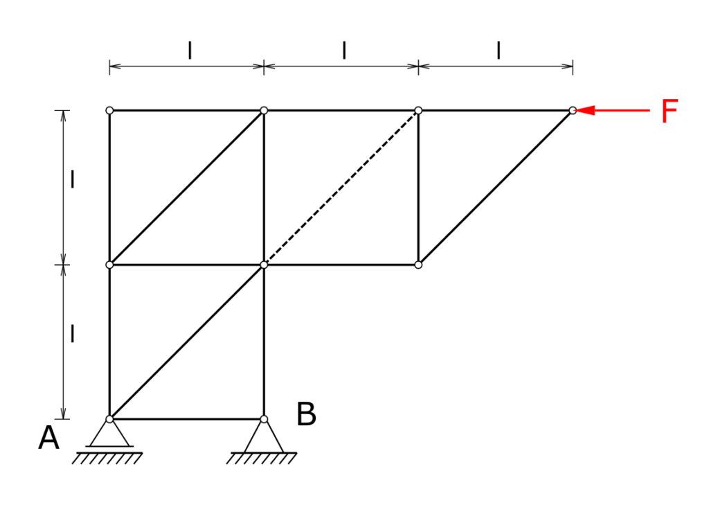
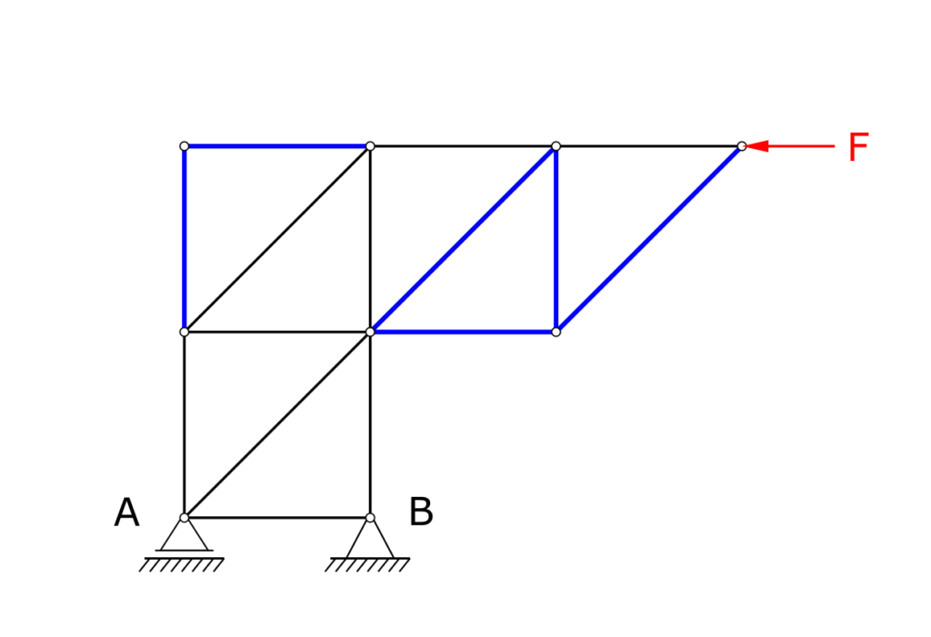
A truss is supported in bearings A and B and is loaded at its outer end by a horizontal force F. The truss itself should be seen as massless. The member force in the member shown in dashed lines must be calculated! The null members of the framework are to be marked!
Solution
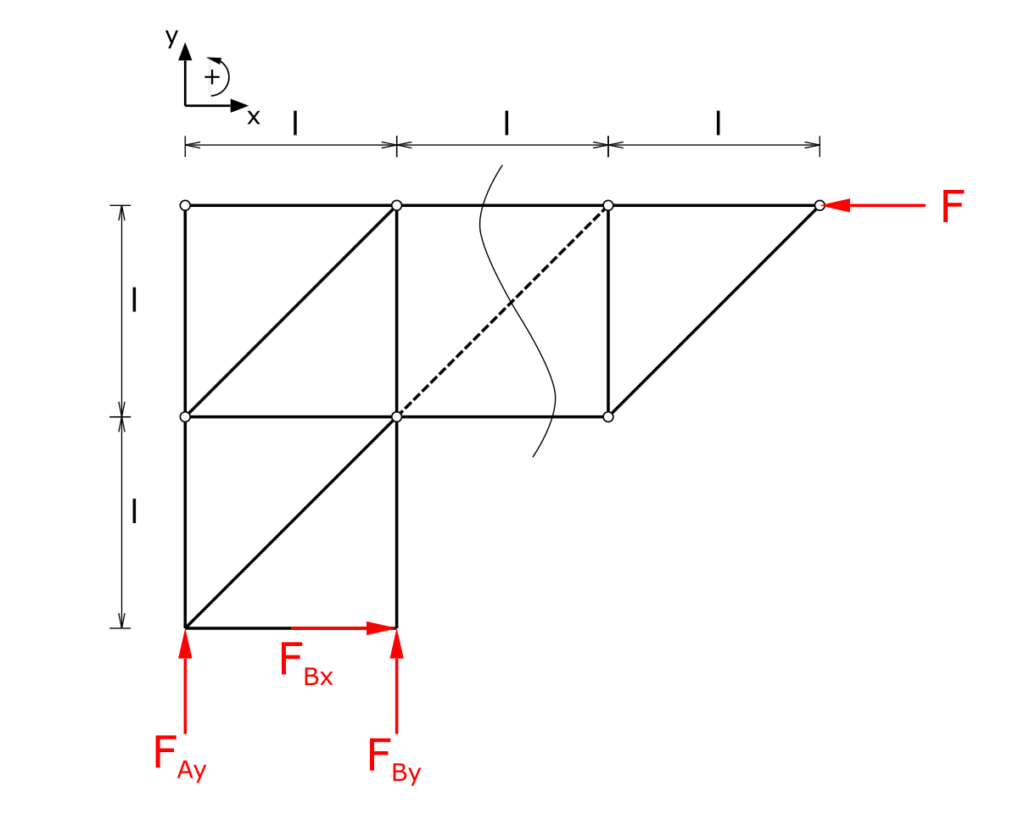
The method of sections is used to determine the member force. The selected cutting line is shown in the following picture. You can freely choose which side of the cut is investigated. In the solution shown here, the side with the bearing reactions is considered, which means that these must be determined in the first step.
Since the members of this framework are only arranged horizontally, vertically and at an angle of 45 °, the results of the trigonometric functions can be noted in abbreviated form.
Bearing loads
Establishing the equilibrium of forces and moments (counterclockwise torques positive):
\[ \tag{1} \sum F_x = 0 = F_{Bx} - F \]
\[ \tag{2} \sum F_y = 0 = F_{Ay} + F_{By} \]
\[ \tag{3} \sum M(A) = 0 = F_{By} \cdot l + F \cdot 2 \cdot l \]
So the bearing loads are
\[ \tag{4} F_{Bx} = F \]
\[ \tag{5} F_{By} = - 2 \cdot F \]
\[ \tag{6} F_{Ay} = 2 \cdot F \]
Zero members, first approach
Before looking at the section, it makes sense to mark the zero members that are immediately recognizable. Zero members are always created when only one member is connected to a node for a certain axis direction x or y. This means that this member cannot pass its load on to any other member.
For the present truss, this applies to the members marked in blue in the following figure.
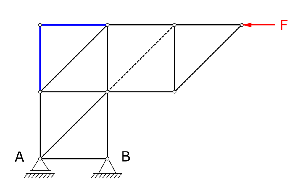
We will find some more zero members later.
Member forces
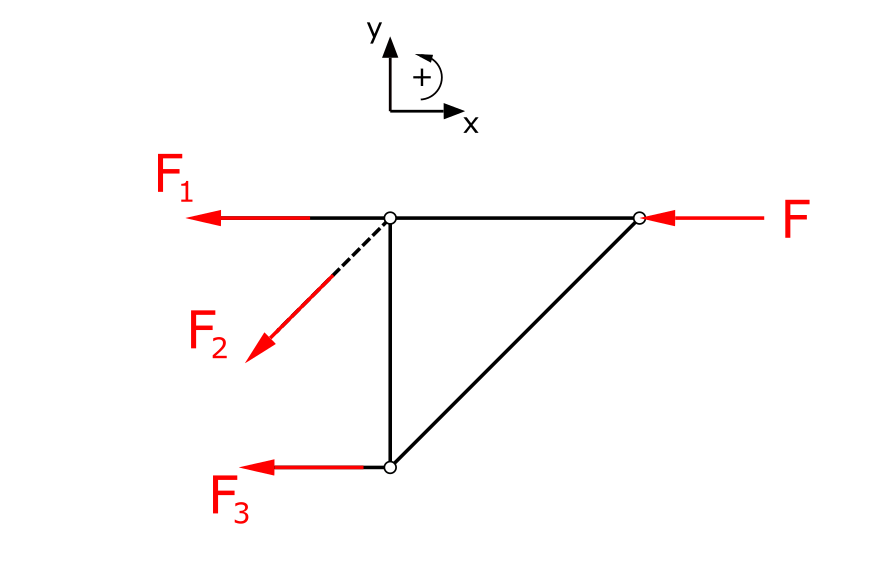
Next, the bar forces (here as tensile forces) are applied to the cut bars and the static equilibrium conditions are established. Point A is chosen as the pivot point.
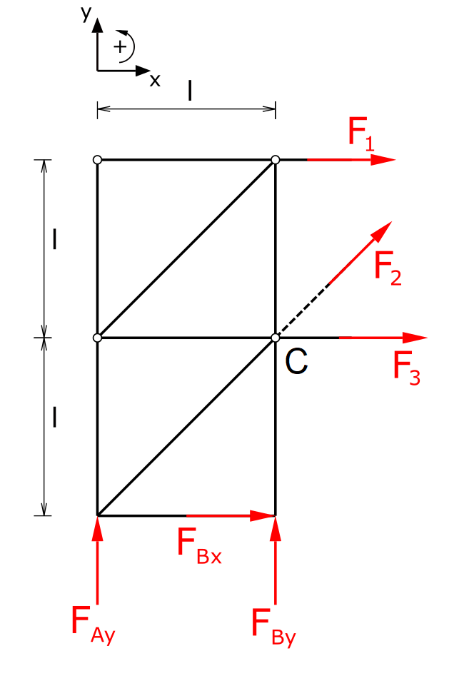
\[ \tag{7} \sum F_x = 0 = F_{Bx} + F_1 + \frac{F_2}{\sqrt{2}} + F_3 \]
\[ \tag{8} \sum F_y = 0 = F_{Ay} + F_{By} + \frac{F_2}{\sqrt{2}} \]
\[ \tag{9} \sum M(A) = 0 = F_{By} \cdot l - F_3 \cdot l - F_1 \cdot 2 \cdot l \]
The member force F2 is determined quickly:
\[ \tag{10} F_2 = 0 \]
So it is another zero member.
The remaining member forces are now calculated. The previous equations could be rearranged and used, or we could consider the moments around point C..
\[ \tag{11} \sum M(C) = 0 = F_{Bx} \cdot l - F_{Ay} \cdot l - F_1 \cdot l \]
\[ \tag{12} F_1 = -F \]
I.e. the considered member is a compression member. The last missing member force results from equation 7.
\[ \tag{13} F_3 = 0 \]
This member is also a zero member.
Zero members, second approach
With the zero members found so far, all nodes of the framework can now be checked again. The following additional null bars result:
The high number of zero members results from the direction of the applied external load. That is, if the acting load contains a vertical component, the distribution of the zero members in the truss also changes.
Alternative consideration
As mentioned above, the static equilibrium could also have been considered for the other side of the cut. In that case the cut element would have looked like this:
This site has an excellent online calculator for 2-dimensional trusses.