
This exercise is about the following questions:
- How to calculate the stress in a rod und load of dead weight?
- How to draw the first circle of Mohr for the uniaxial stress state?
Task
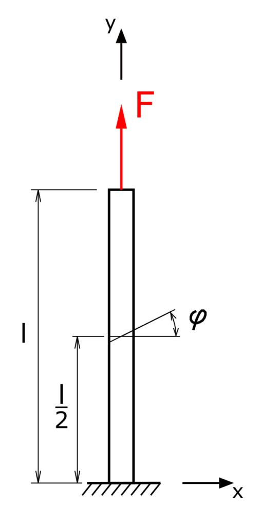
A lean rod with the cross-sectional area q is loaded by the force F and its own weight. The MOHR stress circle is to be drawn for the position y = l / 2. The stresses σφ and τφ are to be determined from the stress circle!
The following parameters are given:
- F = 1 N
- l = 0,4 m
- ρ = 10000 kg/m³
- q = 1 cm²
- φ = 30°
- g = 9,81 m/s²
Solution
In the first step, the internal forces at y = l / 2 must be determined. Since there are no shear forces or moments, there is a uniaxial stress state in the rod.
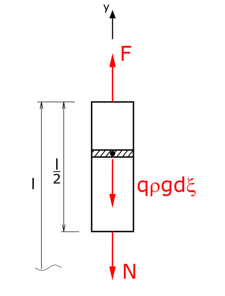
In addition to the normal force at the point y = l / 2, the weight G acts, which is expressed here by integrating the term qρg along the coordinate ξ running in the y direction. Of course, the different dimensions must be taken into account. The stress at the location y = l / 2 is referred to below as σ0.
The balance of forces is made up of this
\[ \tag{1} \sum F_y = 0 = -\int_{l/2}^l{q\cdot \rho \cdot g \,d\xi} - N + F \]
Since the stress is sought for the cross-section under consideration, this equation can be converted into the stress form by dividing it by the cross-sectional area q.
\[ \tag{2} 0 = -\int_{l/2}^l{\rho \cdot g \,d\xi} - \frac{N}{q} + \frac{F}{q} \]
The principal stress σ0 is
\[ \tag{3} \sigma_0 = \frac{N}{q} \]
so equation (2) becomes
\[ \tag{4} 0 = -\int_{l/2}^l{\rho \cdot g \,d\xi} - \sigma_0 + \frac{F}{q} \]
So the sought stress can now be calculated.
\[ \tag{5} \sigma_0 = \frac{F}{q}-\rho \cdot g \cdot \frac{l}{2} \]
For further consideration it makes sense to use Pascal as the unit for the stress. Using generous rounding results in the normal stress to
\[ \tag{6} \sigma_0 = - 10000Pa \]
The first circle of Mohr
The calculated normal stress forms the diameter of the Mohr stress circle. This is to be plotted on the left side of the vertical axis due to the negative stress. The finished circle looks like this:
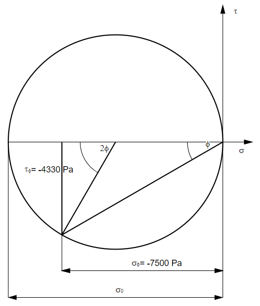
The stresses we are looking for are already included in the above figure.
With this online generator you can draw easily Mohr's first circle.