
This exercise is about the determination of the internal forces of an angled beam and addresses the following questions:
- How to determine the internal forces and moments of a beam?
- How to calculate the shear force, the normal force and the bending moment?
- Where do I have to divide the beam into sections?
- How can I show the gradients of the internal forces and moments as diagrams?
Task
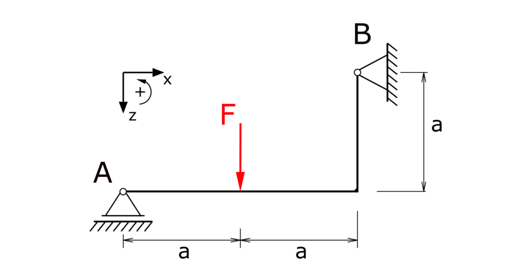
An angled beam with a fixed bearing and a floating bearing is loaded by the force F. The internal forces of the beam have to be determined!
Solution
To calculate the internal forces of the beam, the bearing loads are determined and the beam is divided into three sections. In the following, the shear forces are denoted by Q, the normal forces by N and the bending moment by Mb. Left turning moments are positive.
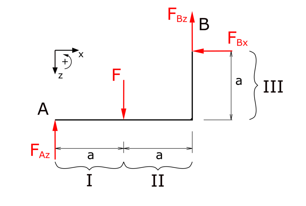
Determination of the bearing reactions
Establishing the equilibrium conditions for forces in the x and z directions as well as for the moments
Note the downward z-axis!
\[ \tag{1} \sum F_x = 0 = -F_{Bx} \]
\[ \tag{2} \sum F_z = 0 = - F_{Az} + F - F_{Bz} \]
\[ \tag{3} \sum M(A) = 0 = - F \cdot a + F_{Bz} \cdot 2a + F_{Bx} \cdot a \]
From this follows
\[ \tag{4} F_{Bx} = 0 \]
\[ \tag{5} F_{Bz} = \frac{F}{2} \]
\[ \tag{6} F_{Az} = \frac{F}{2} \]
Determination of the internal forces in section I
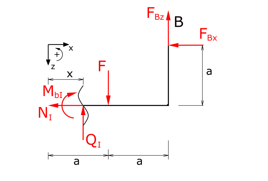
Establishing the equilibrium conditions for forces in the x and z directions as well as for the moments
\[ \tag{7} \sum F_x = 0 = -N_I -F_{Bx}\]
\[ \tag{8} \sum F_z = 0 = -Q_I + F - F_{Bz} \]
\[ \tag{9} \sum M(x) = 0 = -M_{bI} - F \cdot (a-x) + \bcancel{F_{Bx} \cdot a} + F_{Bz} \cdot (2a - x)\]
With the already calculated bearing reactions, the internal forces result
\[ \tag{10} N_I = 0 \]
\[ \tag{11} Q_I = \frac{F}{2} \]
\[ \tag{12} M_{bI} = \frac{F}{2} \cdot x \]
Determination of the internal forces in section II
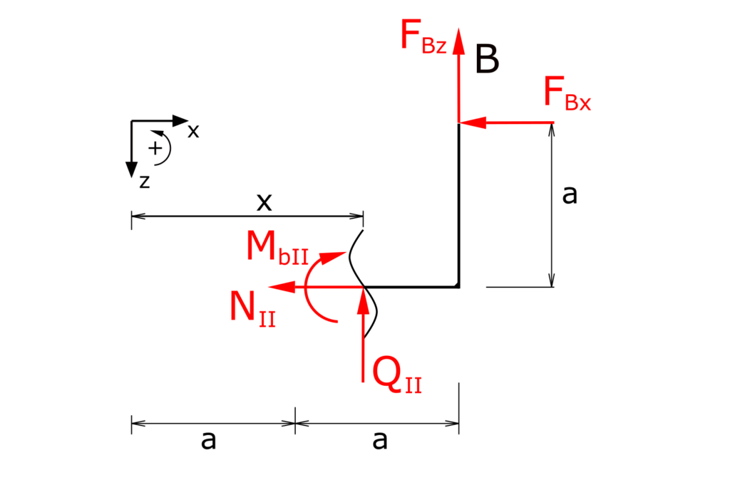
Establishing the equilibrium conditions for forces in the x and z directions as well as for the moments
\[ \tag{13} \sum F_x = 0 = -N_{II} - F_{Bx}\]
\[ \tag{14} \sum F_z = 0 = -Q_{II} - F_{Bz} \]
\[ \tag{15} \sum M(x) = 0 = - M_{bII} + \bcancel{F_{Bx} \cdot a} + F_{Bz} \cdot (2a - x) \]
These internal forces can also be resolved to
\[ \tag{16} N_{II} = 0 \]
\[ \tag{17} Q_{II} = - \frac{F}{2} \]
\[ \tag{18} M_{bII} = \frac{F}{2} \cdot (2a - x) \]
Determination of the internal forces for section III
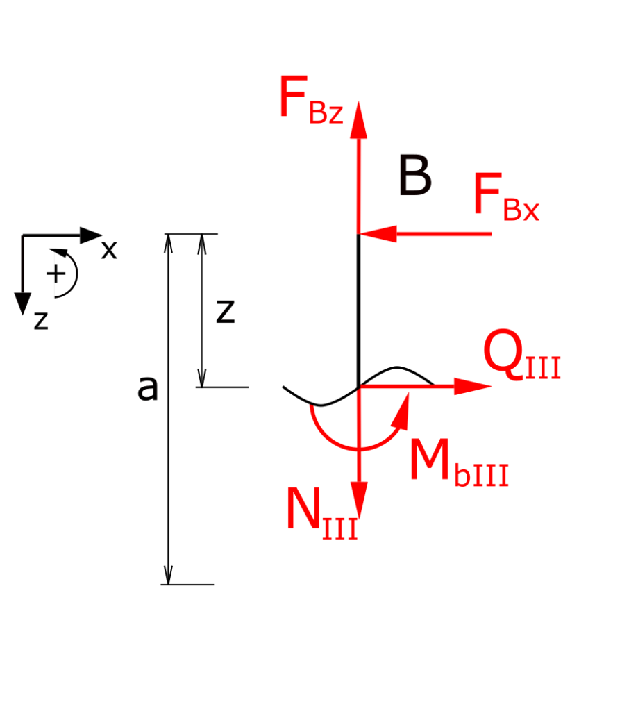
Establishing the equilibrium conditions for forces in the x and z directions as well as for the moments
\[ \tag{19} \sum F_x = 0 = -F_{Bx} + Q_{III}\]
\[ \tag{20} \sum F_z = 0 = N_{III} - F_{Bz} \]
\[ \tag{21} \sum M(z) = 0 = M_{bIII} + \bcancel{F_{Bx} \cdot (z-a)} \]
The internal forces and moments of the third section are
\[ \tag{22} N_{III} = \frac{F}{2} \]
\[ \tag{23} Q_{III} = 0 \]
\[ \tag{24} M_{bIII} = 0 \]
With this all internal forces of the beam are determined.
Graphic representation of the internal forces
The graphical representation of the normal force, shear force and bending moment is as follows:
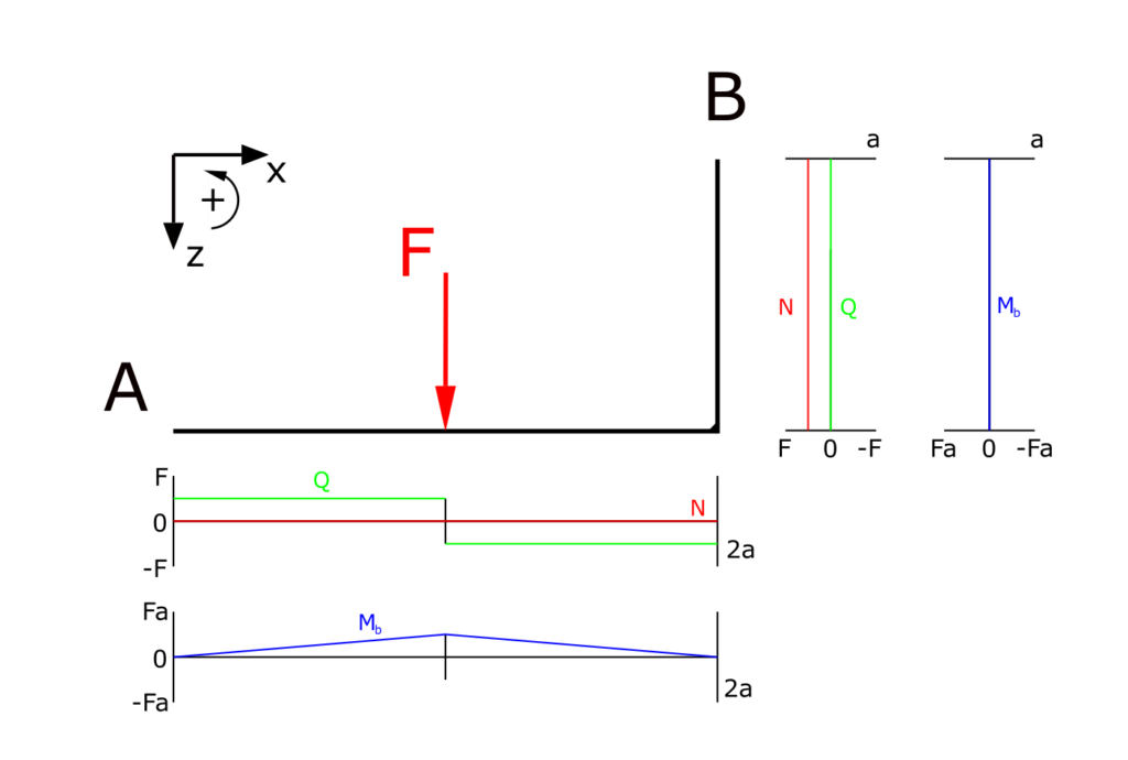
So we can state (for this case), the internal forces of an angled beam are quite similar to an flat beam, but the directions of the normal force and the shear force switch within the angled part of the beam.